Clipping (computer graphics)
This article has multiple issues. Please help improve it or discuss these issues on the talk page. (Learn how and when to remove these messages)
|
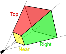
Clipping, in the context of computer graphics, is a method to selectively enable or disable rendering operations within a defined region of interest. Mathematically, clipping can be described using the terminology of constructive geometry. A rendering algorithm only draws pixels in the intersection between the clip region and the scene model. Lines and surfaces outside the view volume (aka. frustum) are removed.[1]
Clip regions are commonly specified to improve render performance. A well-chosen clip[clarification needed] allows the renderer to save time and energy by skipping calculations related to pixels that the user cannot see. Pixels that will be drawn are said to be within the clip region. Pixels that will not be drawn are outside the clip region. More informally, pixels that will not be drawn are said to be "clipped."
In 2D graphics
[edit]In two-dimensional graphics, a clip region may be defined so that pixels are only drawn within the boundaries of a window or frame. Clip regions can also be used to selectively control pixel rendering for aesthetic or artistic purposes. In many implementations, the final clip region is the composite (or intersection) of one or more application-defined shapes, as well as any system hardware constraints
In one example application, consider an image editing program. A user application may render the image into a viewport. As the user zooms and scrolls to view a smaller portion of the image, the application can set a clip boundary so that pixels outside the viewport are not rendered. In addition, GUI widgets, overlays, and other windows or frames may obscure some pixels from the original image. In this sense, the clip region is the composite of the application-defined "user clip" and the "device clip" enforced by the system's software and hardware implementation.[2] Application software can take advantage of this clip information to save computation time, energy, and memory, avoiding work related to pixels that aren't visible.
In 3D graphics
[edit]
In three-dimensional graphics, the terminology of clipping can be used to describe many related features. Typically, "clipping" refers to operations in the plane that work with rectangular shapes, and "culling" refers to more general methods to selectively process scene model elements. This terminology is not rigid, and exact usage varies among many sources.
Scene model elements include geometric primitives: points or vertices; line segments or edges; polygons or faces; and more abstract model objects such as curves, splines, surfaces, and even text. In complicated scene models, individual elements may be selectively disabled (clipped) for reasons including visibility within the viewport (frustum culling); orientation (backface culling), obscuration by other scene or model elements (occlusion culling, depth- or "z" clipping). Sophisticated algorithms exist to efficiently detect and perform such clipping. Many optimized clipping methods rely on specific hardware acceleration logic provided by a graphics processing unit (GPU).
The concept of clipping can be extended to higher dimensionality using methods of abstract algebraic geometry.
Near clipping
[edit]Beyond projection of vertices & 2D clipping, near clipping is required to correctly rasterise 3D primitives; this is because vertices may have been projected behind the eye. Near clipping ensures that all the vertices used have valid 2D coordinates. Together with far-clipping it also helps prevent overflow of depth-buffer values. Some early texture mapping hardware (using forward texture mapping) in video games suffered from complications associated with near clipping and UV coordinates.
Occlusion clipping (Z- or depth clipping)
[edit]In 3D computer graphics, "Z" often refers to the depth axis in the system of coordinates centered at the viewport origin: "Z" is used interchangeably with "depth", and conceptually corresponds to the distance "into the virtual screen." In this coordinate system, "X" and "Y" therefore refer to a conventional cartesian coordinate system laid out on the user's screen or viewport. This viewport is defined by the geometry of the viewing frustum, and parameterizes the field of view.
Z-clipping, or depth clipping, refers to techniques that selectively render certain scene objects based on their depth relative to the screen. Most graphics toolkits allow the programmer to specify a "near" and "far" clip depth, and only portions of objects between those two planes are displayed. A creative application programmer can use this method to render visualizations of the interior of a 3D object in the scene. For example, a medical imaging application could use this technique to render the organs inside a human body. A video game programmer can use clipping information to accelerate game logic.[3] For example, a tall wall or building that occludes other game entities can save GPU time that would otherwise be spent transforming and texturing items in the rear areas of the scene; and a tightly integrated software program can use this same information to save CPU time by optimizing out game logic for objects that aren't seen by the player.[3]
Algorithms
[edit]- Line clipping algorithms:
- Polygon clipping algorithms:
- Rendering methodologies
See also
[edit]- Boolean operations on polygons
- Bounding volume
- Clip space
- Distance fog
- Guard-band clipping
- Hidden-surface determination
- Pruning (decision trees)
- Visibility (geometry)
Further reading
[edit]- GPU Gems: Efficient Occlusion Culling [3]
- Clipping in Java AWT:
java.awt.Graphics.clipRectJavaDoc [2] - Clipping in UIKit for iOS (2D):
UIRectClip - Clipping in SceneKit for iOS (3D):
SCNCamera(Adjusting Camera Perspective) - Clipping in OpenGL: OpenGL Technical FAQs: Clipping, Culling, and Visibility Testing[4]
References
[edit]- ^ Bertoline, Gary; Wiebe, Eric (2002). Fundamentals of Graphics Communication (3rd ed.). McGraw-Hill. p. G-3. ISBN 0-07-232209-8. Retrieved 2015-01-04.
- ^ a b "java.awt.Graphics.clipRect". Oracle. 2014.
- ^ a b c Sekulic, Dean (2004). "Efficient Occlusion Culling". GPU Gems. Pearson. Archived from the original on 2013-06-05. Retrieved 2015-01-02.
- ^ Paul Martz (2001). "Clipping, Culling, and Visibility Testing". OpenGL.org. Retrieved 2015-01-02.
